To perform in vivo measurements and to steadfastly analyze blood gases, a small, stable, accurate and bio-compatible sensor is needed that can be inserted in the blood flow of an artery through an arterial cannula and remain in place for several days. Additional, it has to be low cost so that it could be used as a disposable item. Innovation in fiber-optics and the development of pH and oxygen sensitive dyes have made such a sensor possible.
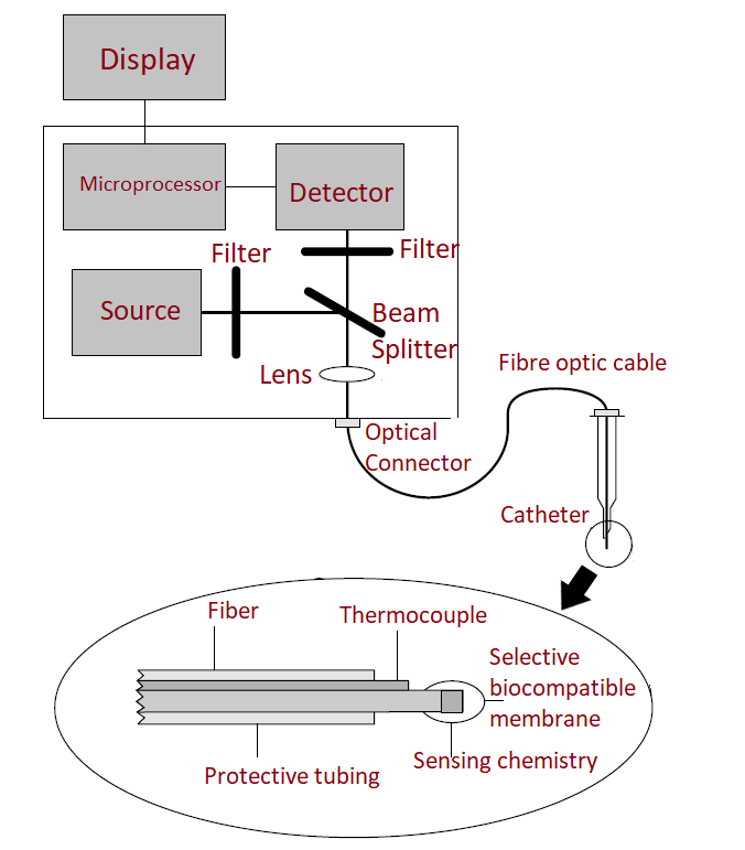
An illustration of a fiber-optic based blood gas analyzer is shown below:

The sensors are interfaced with an electro-optic monitor. The monitor supplies the excitation light, which may be from a monochromatic source such as a diode laser or a broadband source like a xenon lamp whose light is filtered to provide a narrow bandwidth of excitation. Two wavelengths of light are provided, one wavelength is sensitive to changes in the species to be measured, while the other wavelength is unaffected by changes in the analyte concentration. The unaffected wavelength serves as a reference and is used to compensate for fluctuations in the source output and detector efficiency. The light output from the monitor is coupled into a fiber-optic cable through appropriate lenses and optical connectors. The cable is sufficiently long to permit easy patient access by allowing the monitor to be placed at a distance. The cable is sufficiently long to permit easy patient access by allowing the monitor to be placed at a distance.
Also read: Blood Glucose Sensors
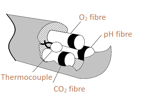
The sensor assembly contains three fibers that measure blood CO2, O2 and pH bundled together with the thermocouple.

The optical-fiber is approximately 10 cm long and also has a thermocouple or thermistor wire running alongside the fiber to measure temperature near the sensor tip. The temperature correction is required for optical blood gas sensors. The solubility of the gases namely O2 and CO2 in the sensing material is a function of temperature and the optical properties of the sensing chemistry also change as the temperature varies. The fibers and the temperature sensor are covered in a protective tubing to contain any fiber fragments in case of sensor breakage.
Find out more about: Fingertip Pulse Oximeter Blood Oxygen Saturation Monitor
Each fiber is very thin and coated at the tip with a specific chemical dye. When light of a known wavelength strikes the dye, the dye fluoresces, giving off light of a different wavelength. The fluorescent emission changes in intensity as a function of the concentration of the analyte (O2, CO2 or pH) in the blood. The emitted light travels back down the fiber to the monitor where it is converted into an electrical signal by using a solid state detector or a photomultiplier. The signal is amplified before it is given to a digitizer. Signal processing to relate the light intensity to the analyte concentration is achieved using a microprocessor and is displayed digitally. Since a detector produces noise or dark current when it is not illuminated, accurate signal measurements need the ambient light be subtracted from the total signal, therefore a signal measurement is made with the flash lamp off. This ambient light is subtracted from signal by correlated double integration circuits. One more factor that affects accurate blood gas calculations is the background fluorescence of the materials in the optical block. This value is achieved by measuring the current developed by the detector when no sensor is connected. As with ambient light, the background fluorescence is subtracted from the signal measurement.
Related: The General Principle of Fiber Optic-based Sensor

Leave a Reply
You must be logged in to post a comment.